
Connecting the front panel connectors to your motherboard can be a daunting task, especially if you’re a first-time builder. But fear not, as it is not as complicated as it seems. In fact, understanding it can be a great opportunity to improve your familiarity with the inner workings of your PC.
Front Panel Connectors are responsible for linking the computer’s power button, reset switch, LED lights, and USB ports to the motherboard. In this blog, we’ll walk you through the steps you need to follow to connect your front panel connectors accurately. So, grab a screwdriver and let’s dive in!
Identify Front Panel Connectors
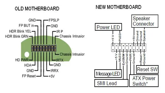
When building your own PC, one important step is to connect the front panel connectors to the motherboard. These connectors are responsible for powering on the computer, as well as controlling the reset button, HDD LED, power LED, and more. To ensure that the connectors are plugged in correctly, it is important to refer to the front panel connector diagram provided in the motherboard manual.
This diagram will illustrate the location of each connector and the corresponding pin on the motherboard. Although it may seem daunting, connecting the front panel connectors is actually quite simple and can be done with just a few easy steps. By consulting the provided diagram and carefully plugging in each connector, you will be well on your way to successfully building your very own PC.
Examine the Motherboard
When examining a motherboard, it’s important to know how to identify front panel connectors. These connectors are what allow you to connect your computer’s power button, reset button, and other front panel features. In order to find them, you’ll need to look for a set of small pins on the bottom right side of the motherboard.
These pins will often be labeled with abbreviations or symbols that indicate what they’re used for. Some common labels you might see include PWR_SW (power switch), RST_SW (reset switch), HDD_LED (hard drive activity indicator), and PWR_LED (power indicator). By connecting these wires to the appropriate pins on your motherboard, you’ll be able to control your computer’s front panel features.
Remember to consult your motherboard manual for specific instructions on which pins to use for each function.
Read the Motherboard Manual
When it comes to building a computer, one of the most important things you can do is read the motherboard manual. This booklet is a valuable resource that can help you identify the front panel connectors on your motherboard. These connectors are the small pins that you’ll need to connect to your case’s power button, reset button, and other front-facing ports.
The manual will typically include a diagram that shows the location and orientation of these connectors, so make sure you study this carefully before attempting to connect them. It’s important to get these connections right, as an incorrect connection could prevent your computer from starting up or even cause damage to your hardware. So, take the time to read the manual thoroughly and double-check your connections before booting up your machine.
It’s better to be safe than sorry when it comes to building a PC!
Power Connectors
Connecting front panel connectors to a motherboard can often seem like a daunting task, but with the help of a diagram and some basic knowledge, it can be easily accomplished. Power connectors, in particular, are an essential component of the front panel, allowing the computer to power on and off. The diagram will typically show the location of these connectors, which usually have positive and negative labels next to them.
It’s important to take the time to ensure that these connections are made correctly, as incorrect wiring can lead to malfunctions or even damage to the computer. By following the diagram, double-checking each connection, and taking things one step at a time, even the most inexperienced computer user can successfully connect the front panel power connectors to the motherboard.
Connect Power LED Headers
Power LED headers, power connectors When setting up your computer, it’s important to connect the power LED headers to ensure that everything runs smoothly. These small connectors are responsible for lighting up the power button and indicating that your computer is turned on. They can be easily connected to your motherboard with the included cables.
Simply align the positive and negative pins on the connector with the corresponding pins on the motherboard, and gently push the connector into place. It’s important to double check that the connectors are securely in place to prevent any issues with power or performance. The power LED headers may seem like a small detail, but they play an important role in keeping your computer up and running.
So take your time when connecting them and double check your work to ensure everything is properly connected.
Connect Power Switch Header
When it comes to building a PC, it’s crucial to know how to connect power switch headers properly. These tiny connectors are responsible for turning your computer on and off, so proper installation is vital to ensure that your system runs smoothly. Power switch headers are typically located on the motherboard and are identified by labels such as “PWR_SW” or “Power Switch.
” To connect them, you need to first identify the positive and negative connectors on the header and then match them up with the corresponding connectors on your power switch. Some connectors may also have a ground wire, which should be connected to the appropriate pin on the header. Once the header is connected, you can then proceed to power up your PC and start using it.
Overall, understanding how to properly connect power switch headers is a crucial step in building a PC that runs smoothly and reliably, so be sure to take the time to familiarize yourself with this process before you start building.
Connect Reset Switch Header
When building a PC, one of the crucial components to consider is the power connectors. One such connector is the reset switch header, which is responsible for resetting the system in case of a hang or freeze. The connector consists of two or three pins, and its placement on the motherboard can vary depending on the model.
Connecting the reset switch header is a relatively simple process, but it’s essential to consult the manual for guidance and ensure correct placement. The reset switch header may seem like a small component, but it’s critical in ensuring a smooth and functional PC. So, if you’re planning to build your own PC, make sure to pay close attention to the power connectors, including the reset switch header.
Connect HDD LED Header
Connecting the HDD LED header is an important step when building a computer. The HDD LED header is responsible for indicating the activity of your hard drive. To connect the HDD LED header, you’ll need to locate the port on your motherboard labeled “HDD LED”.
Next, take the HDD LED connector and align it with the pins on the motherboard, making sure that the positive and negative wires are correctly aligned. The positive wire is usually labeled with a plus sign or a number one, while the negative wire is labeled with a minus sign or a number two. Once you’ve aligned the connector, gently push it onto the pins until it’s firmly in place.
It’s essential to properly connect the HDD LED header as it can help you diagnose issues with your hard drive in case it’s not functioning correctly. So, don’t forget to double-check your connections before powering on your computer.
Audio and USB Connectors
Connecting front panel connectors to the motherboard can be a bit daunting, but with the right diagram and a little patience, it can be done. One of the most confusing tasks is connecting the audio and USB connectors. Motherboard manufacturers typically label the connectors with letters or symbols that correspond to their function.
For example, the audio connectors may be labeled AAFP or HD Audio, while the USB connectors may be labeled USB 0 or USB 0.
Once you have identified the connectors, refer to your motherboard’s user manual to determine their exact placement on the board. Make sure to align the connectors correctly with the pins to avoid damage to your computer or the connectors themselves. With a little care and attention to detail, connecting front panel connectors to your motherboard can be done quickly and easily.
Connect Audio Connectors
When it comes to audio and USB connectors, it may seem a little intimidating at first, but once you get the hang of it, it’s actually pretty simple! Let’s start with audio connectors. The most common audio connector is the 5mm jack, often seen on headphones and speakers.
This type of connector is also known as a mini-jack or TRS connector, which stands for Tip, Ring, Sleeve. The “tip” carries the left audio channel, the “ring” carries the right audio channel, and the “sleeve” is the ground connection. Another type of audio connector is the RCA connector, which consists of two plugs – one for the left audio channel and another for the right audio channel.
As for USB connectors, there are four types: Type-A, Type-B, Type-C, and Mini-USB. Type-A is the most common type and is often seen on laptops and desktops. Type-C is a newer, reversible connector that can be plugged in any way.
Mini-USB is a smaller version of Type-A and is commonly used for cameras and portable devices. With these basic knowledge about connectors, you’ll be able to connect your devices with ease!
Connect USB Connectors
Connecting audio and USB connectors can be a little intimidating for those who may not be tech-savvy, but fear not – it’s actually quite easy! When it comes to audio connectors, the most common type you’ll see is the 5mm jack. This is the small, round plug that you’ll find on headphones, speakers, and microphones.
To connect them, simply insert the jack into the corresponding port on your device. USB connectors, on the other hand, can be a bit more varied. Some devices may have standard USB-A ports, while others may have USB-C or micro-USB.
To connect, simply plug the USB connector into the corresponding port on your device. It’s important to note that some devices may require specific drivers to function properly when connected via USB. Overall, connecting audio and USB connectors is a quick and simple process that anyone can do with ease.
So, the next time you want to enjoy your favorite tunes or transfer data from your device, go ahead and connect those connectors!
Final Steps
Connecting the front panel connectors to the motherboard can be a daunting task, especially for beginners. However, with a little patience and some guidance, it can be done easily. First, locate the front panel connectors on your computer case.
They are usually found near the bottom front of the case and are labeled accordingly. Next, refer to your motherboard manual to identify the location of the front panel header. Once you have identified the header, carefully align the connectors with the pins on the header.
It is important to note that each pin has a corresponding slot and the connectors must be inserted carefully to avoid damaging the pins. Finally, plug in the connectors to their corresponding slots and you’re done. It’s important to test your connections before closing up the case to ensure everything is working as it should.
With this simple diagram on how to connect front panel connectors to the motherboard, anyone can do it with ease and confidence.
Check the Connection
When you’re experiencing connectivity issues, the first thing to check is the connection. Ensure all cables and cords are plugged in correctly and securely. Make sure your router is functioning properly and is positioned in a central location in your home.
Also, ensure there are no potential interference sources such as large appliances or thick walls that might be affecting your Wi-Fi signal. Take a look at your device’s settings and ensure you are connected to the correct network and have entered the correct login credentials. In some cases, restarting your device or router can help fix connectivity issues.
By taking these final steps and checking the connection, you can troubleshoot and fix connectivity problems quickly.
Power Up the Computer
Now that you have successfully installed the hardware and connected all the necessary cables, it’s time to power up your computer! Before pressing the power button, make sure all the peripherals like mouse, keyboard, and monitor are connected properly. Once you’re confident that everything is in place, take a deep breath, press the power button, and wait for the startup process to begin. The computer will load all the necessary software and drivers, and you’ll be prompted to create a user account and configure your settings.
With everything set up, you’re now ready to start using your brand new computer! Remember to save important documents and files regularly and keep your computer’s antivirus software up to date to ensure smooth functioning and protection against threats. Congratulations, you’ve successfully set up your very own computer system!
Conclusion
In conclusion, correctly connecting front panel connectors to a motherboard may seem daunting at first, but with a bit of patience and attention to detail, anyone can be a pro! Just like a puzzle, follow the diagram and fit each connector into its corresponding slot. And just like building a tower out of blocks, remember to start with a solid foundation – that means double-checking the orientation of each connector and ensuring they are securely fastened. Once you’ve completed the task, sit back and admire your handiwork, knowing that you’ve successfully conquered the motherboard/front panel connection challenge!”
FAQs
What are front panel connectors?
Front panel connectors are a set of wires that run from the power button, reset button, and LED lights on the front of your computer case to the motherboard.
How do I know which connector goes where on the motherboard?
Consult your motherboard manual, which should have a diagram and description of each connector and where it should be plugged in.
What should I do if there are extra connectors that I don’t need?
It’s okay to leave them unconnected, as they may be for additional features that your particular motherboard does not support.
What happens if I connect the front panel connectors incorrectly?
Connecting the connectors incorrectly may result in your computer not being able to turn on or function properly. Always consult your motherboard manual to ensure proper connection.